BuddyLab

Desk Companion Manual

Desk Companion assembly guide

This step-by-step guide explains the basic Desk Companion robot build using the ESP32-C3, the 0.96-inch or 1.3-inch OLED display and the capacitive touch sensor. It also points to the next optional upgrades, including a vibration motor and a piezo buzzer.

Manual format Basic build guide
Main board ESP32-C3 Super Mini
Core modules OLED + touch sensor

Wiring Diagram

Base desk companion robot wiring: ESP32-C3 + OLED + touch sensor

Base wiring diagram for the Desk Companion

The first step is to wire the 0.96-inch or 1.3-inch OLED display, the ESP32-C3 and the capacitive touch sensor together. This is the base electronic assembly for the Desk Companion robot.

  • Display: GND to GND, VCC to VCC (3.3V), SCL to GPIO9, SDA to GPIO8
  • Touch sensor: VCC to VCC (3.3V), GND to GND, OUT to GPIO7
  • Color guide: red = VCC 3.3V, black = GND, yellow = GPIO

Important

ESP32-C3 placement check

Make sure the ESP32-C3 is placed correctly on its breakout board. Use the 5V pin as a visual reference and verify that the USB-C port is on the same side as the blue header pins marked 5V.

ESP32-C3 orientation reference
  • Use the 5V pin marking as your first check point
  • The USB-C connector should sit on the same side as the 5V header row
  • If orientation is wrong, the wiring diagram will not match the build

Firmware Install

Flash the firmware for the basic build

01

Open the firmware page

Firmware installation page preview

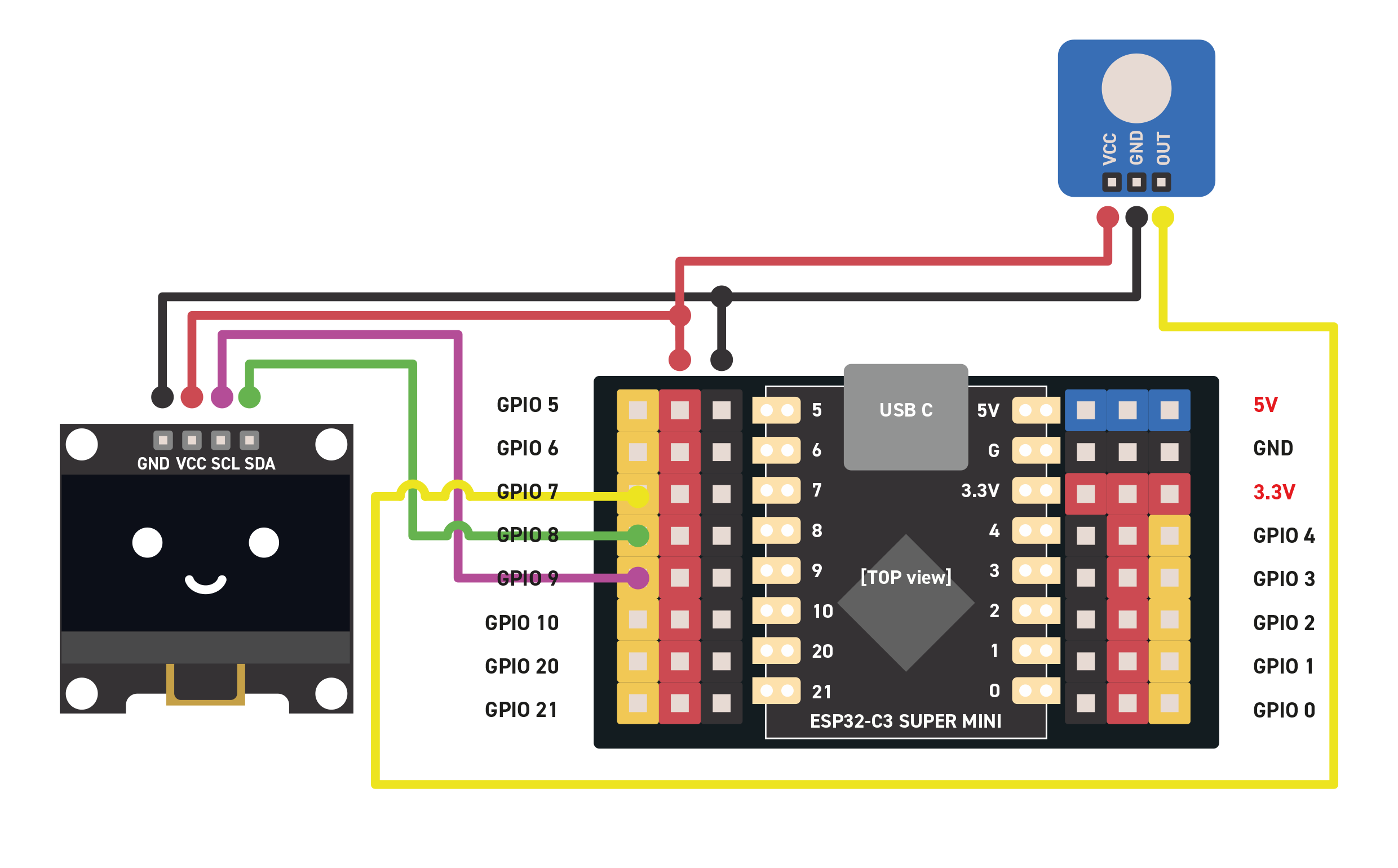
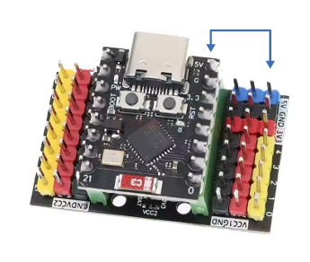
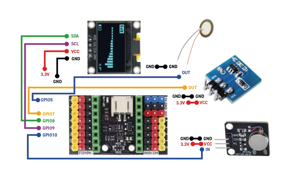
At this stage of the assembly, you can already install the firmware on the ESP32 to verify that everything is working correctly. Connect your ESP32-C3 to your computer with a USB-C cable, then open the main site.

02

Click "Install the firmware"

Firmware install button preview

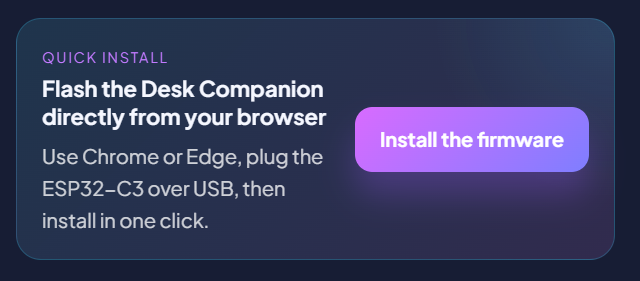
Click the install button on the website and select your ESP32-C3 board when it appears in the browser device list.

03

Select the board

ESP32 board selection preview

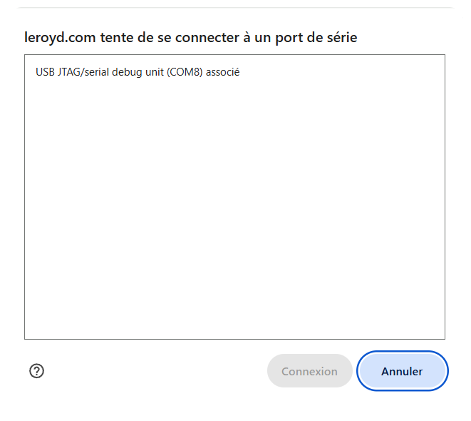
Choose your board from the serial device picker and connect to it to continue the flashing process.

04

Click the installer entry

Installer entry preview

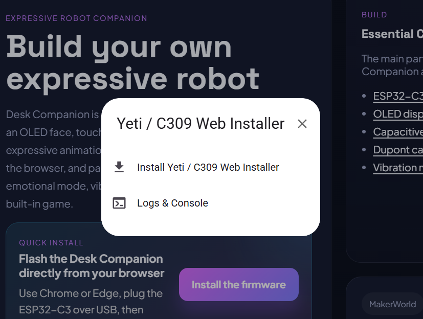
Click the text shown in the installer window, "Install Yeti / C309 Web Installer", to start the installation process.

05

Wait for installation to finish

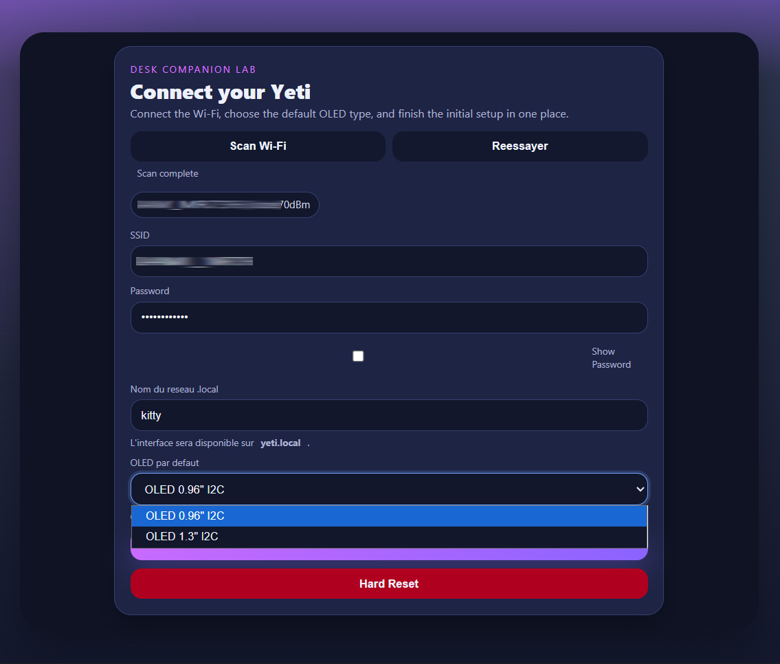
Finish by launching the installer and wait for the success message. Once it is done, the process is complete and the selected OLED display should show the expected setup screen.

Quick setup

Finish the first configuration

After the firmware is installed, the Desk Companion still needs one short network setup before the main control page becomes available.

Connect to Yeti_Config

After reboot, join the Yeti_Config Wi-Fi network from your phone or computer.

Open the config page

If the portal does not open automatically, go to 192.168.4.1 in your browser.

Choose your Wi-Fi

Scan for networks, select your Wi-Fi and enter the password.

Set local name and screen

Choose the .local address and select the OLED model used by your build, with 0.96" as the default option or 1.3" if needed.

Connect and reboot

Click Connect, then wait for the Desk Companion to restart on your Wi-Fi.

Open the control page

Open your chosen .local address to access the main interface and test expressions.

On this screenshot, the Yeti name has been changed to "kitty".
To access the interface, you would open "kitty.local".

Go further

Optional vibration motor and piezo wiring

Once the base build is working, you can add the vibration motor and the piezo module for a more expressive desktop companion.

Extended assembly diagram with optional modules
Module VCC GND Signal
Piezo buzzer 3.3V GND GPIO5
Vibration motor module 3.3V GND GPIO10

These two modules are optional and are added on top of the base build shown earlier in this guide.

Important

Basic build troubleshooting

  • ESP32 breakout mounted upside down on the breakout board
  • Incorrect wiring compared with the diagram
  • Faulty USB cable or charge-only cable
  • Defective display module
  • Using the wrong display model
  • Display address difference such as 0x3C or 0x3D

Next Step

Continue on the main site

Use the main site to launch the firmware install, then return to MakerWorld for the full public project page and printable files.